Crouching Schema Hidden Dragon


The SchemaMapper transformer is infamous for being complex in both concept and practice; perhaps to the point where a mythical dragon scares off some users without their even trying it out.
However, to avoid this transformer is to miss out on a great deal of functionality; plus with the advent of dynamic translations – where workspaces are created to handle any data structure – there needs to be a method by which to handle the schema of these unknown datasets, and the SchemaMapper is that method.
Look?! Our SchemaMapper dragon isn’t so scary. So, the next few postings will (hopefully) help users by clarifying exactly what the SchemaMapper is designed to do, and how it can be used in your quest for the perfect spatial data translation.
Definition of Schema
Before starting let’s define exactly what I mean by schema. I’ll take this information directly from the FME Desktop training manual, which explains all. Schema – if you don’t know the term – is really just another word for Data Model. Each spatial dataset has its own data model (schema) which is a physical representation of the data. Of the different components of this structure the ones I really want to concentrate on are:
- Feature Types (FME’s term for “layers”, “classes” or “tables”)
- User Defined Attributes
Schema Mapping
So the source schema for a dataset is a physical schema which represents what we have. The destination schema for a dataset is a logical schema (ie it doesn’t necessarily exist yet) which represents what we want to get.
The act of connecting the source schema to the destination schema, to define which source components should end up where, is known as Schema Mapping.
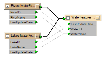
In FME Workbench, Schema Mapping is usually done by drawing connecting lines between the source and destination schema, like so:
Above: This example shows River and Lake features being merged into a single output type called WaterFeatures. Note how the darker line represents Feature Type mapping and each lighter line represents Attribute Mapping.
However, an alternate method to these connection lines is to use the SchemaMapper transformer.
The SchemaMapper
The SchemaMapper is simply a transformer which replaces the connecting lines of manual Schema Mapping with an external lookup table of mappings.
However, confusion arises because there are so many tasks to which the transformer can be put; most of which appear fairly complex and any of which can be defined within the wizard. So, although the user may not be aware of this, many fields and dialogs in the wizard are not applicable to the task at hand and can safely be ignored.
There are three key dialogs in the SchemaMapper wizard.
- Mapping Fields is the dialog in which to define attribute mappings
- Index Mapping is the dialog in which to define feature type mappings
- Filter Fields is a dialog which represents a sort of “Where” clause for the mappings.
Attribute Mapping with the SchemaMapper
For the remainder of this post, let’s take a simple case of attribute mapping.
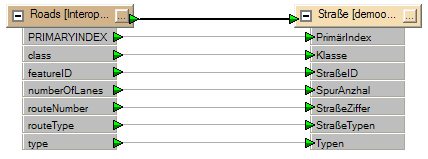
Above: This example shows renaming English attributes to German, so the data can be passed to a German speaker. I apologize for the potentially awful German translation which I interpreted from an online dictionary.
Using the above English>German example the source attribute “class” gets mapped to the destination attribute “Klasse”.
To replicate this using the SchemaMapper all I need is a simple CSV (Text) file containing a header line and the field names:
SourceAttribute,DestinationAttribute
class,Klasse
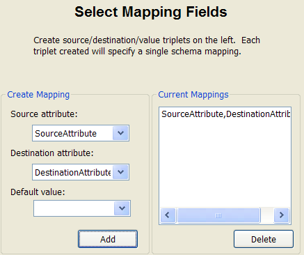
When I use this in the SchemaMapper I can ignore the Filter Fields dialog, and the Index Mapping. The only dialog I need to use is to Select Mapping Fields:
All this means is that when FME finds an attribute whose name is defined in the SourceAttribute column of my CSV file, then it renames it to the name in the corresponding DestinationAttribute column. In this example. if FME finds an attribute called “class” then it gets renamed to “Klasse”
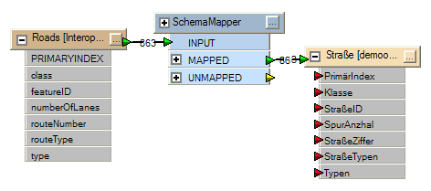
Now I can enter all my other mappings (eg featureID to StraßeID) into the CSV file to complete the mapping of attributes from one schema to another. Workbench won’t show these automatically (see below where the destination attributes are still red) but FME will still recognize and write the correct attributes for my destination schema.
There. That wasn’t so bad. But I know you’re probably thinking, “Why use the SchemaMapper? All you’ve really done is replicate what was already there”. Well, there are a number of good reasons:
- Defining mappings in a text file makes it easier for non-FME users to update the process. Provided the destination schema exists you can edit the text file without changing the workspace!
- If you use a dynamic workspace (more on that later) you can edit the mappings without ever having to do it in Workbench (whether or not the schema already exists in the workspace!)
- If you used the Filter Fields dialog in the SchemaMapper you could put a ‘where’ clause on the mapping (for example, if numberOfLanes = 2 then featureID becomes StraßeID, if numberOfLanes = 4 then featureID becomes AutobahnID)
- If there were multiple source Feature Types then you could route all them into the same SchemaMapper and have them mapped simultaneously
Is that enough? Probably for the moment. Think about the above and in another posting I’ll examine Feature Type mapping, and how to combine it with a fanout for maximum effect.
But if you are a sucker for punishment, then here are a few links to some more reading:
- http://www.fmepedia.com/index.php/SchemaMapper (A description plus many examples and use cases)
- http://www.fmeuc.com/archive/2009downloads/workshops/FMEUC09-StretchingFMEWorkshop.pdf (although not listed in the contents, page 22 onwards of this user conference workshop is all about the SchemaMapper)
Regards


